The first step in planning any kind of heating system for your home is to establish how much heat you need. How do you do this?
The standard procedure is to measure all of the spaces involved. You then calculate how much heat will be lost when they are fully heated in cold weather conditions. Within the UK “cold weather” is generally taken to mean an outside temperature of minus 1ºC.
It’s useful to have a grasp of heat loss principles, but if you prefer to skip the maths, most stove shops will do them for you (including Backwoodsman; call us if you would like to discuss your requirements.)
The following section explains heat loss basics.
1. Heat Loss - conductive
 During the summer months indoor and outdoor temperatures are often exactly equal. In this situation no heat is lost from our buildings. (A.)
In winter however things are different. As the weather gets colder we turn on our heating system in an effort to maintain our rooms at near summer temperatures – but unfortunately it is never possible to do this without losing heat continuously to the colder air outside. (B.)
The seepage of heat through solid partitions (walls and windows) is known as “conductive heat loss” and increases as the temperature differences on either side of the partitions become more extreme. For instance on a mild autumn evening, the outdoor temperature may only be 7ºC. lower than our room temperature, whereas on a frosty night the difference will be more like 21ºC. Where the temperature difference increases three-fold (as in this example,) conductive heat loss also increases three-fold, regardless of how well insulated our home is.
The convention in the UK is to calculate heat loss on the basis of an external temperature of -1ºC. (or -2ºC. in some parts of Scotland.)
This means that in freakishly Arctic conditions, your heating system simply won’t provide you with enough comfortable heat. But it seldom makes sense to design for a short-term situation that crops up only once in a blue moon. A better strategy is to have one or two auxiliary heaters (perhaps mobile gas or electric fan heaters) you can call on for the odd occasions when they are needed.
2. Heat Loss - U values
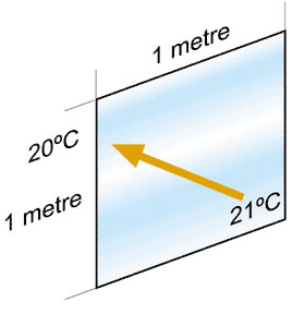
The conductive heat loss of a material is expressed as its “U” value. If we measure the amount of heat lost through a pane of glass one metre square when the temperature on the outside of pane is one 1ºC. cooler than the inside, we get a figure of around 5.4 watts. That is its “U value.”
So now we can solve a simple problem;-
What is the heat loss for a single-glazed window 2.07m x 1.63m in a room heated to 21ºC. against an outside temperature of -1ºC.?
Answer; 2.07 x 1.63 x 5.4 x 22 = 400 watts.
(For interest, a modern, argon-filled double glazed panel with a “U” value of 1.6 would bring the heat loss down to 119 watts.)
As we have seen, the arithmetic involved is simple but rather tedious for a whole house since it becomes necessary to go round calculating the surface areas for each type of material used in each room. Most heating engineers now use a slide-rule or computer program designed to simplify the process.
| construction | “U” value |
| 280mm cavity wall | 1.5 |
| 280mm foam-filled cavity wall | 0.57 |
| 230mm solid brick | 2.1 |
| inner partition walls | 2.04 |
| ceiling in house (ground floor) | 1.59 |
| ceiling in house (first floor) | 0.45 |
| ceiling in bungalow | 0.45 |
| windows, wood | 4.3 |
| windows, metal | 5.6 |
| floors (varying according to size of room and number of outside walls) | |
| wood floor | 0.8 – 1.3 (suspended wood floor with 25mm fibreglass) |
| solid floor on earth | 0.5 – 1.0 (insulation between boards and joists) |
| air changes: Halls approx 2 per hour. All other rooms 1.5 per hour except bedrooms which are typically 1 per hour. | |
3. Heat Loss - inside and outside partitions
 The illustration at right shows a simplified plan view of conductive heat loss.
Notice that heat loss is greater from rooms A, B,G & H because these are corner rooms with two outside walls. By contrast, rooms E,D & F have only one outside wall, so in this situation they are easier rooms to heat.
The other thing to notice is that for the purposes of illustration the front hall and corridor (C.) is unheated, leading to some leakage of heat from all rooms into this area. This shows that the temperatures in adjacent rooms must be taken into account when conductive heat losses are being calculated.
There are two other points to bear in mind;-
• The true position in a house is of course three-dimensional. Therefore heat loss must be calculated for the floor and ceiling as well as for partitions. Upper floors in particular tend to benefit from the effect of heat seeping upwards from the rooms below, but the heat gained this way can usually only be guessed at.
• An outside wall is still an outside wall for the purpose of heat loss calculations even where there is a garage or outhouse attached to it. Unless of course the garage or outhouse is being heated.
4. Heat Loss - floors
 Another factor to be aware of is the varying rate of heat loss from the floor at ground level. The illustration at right shows the situation with a solid concrete floor. Here most heat loss occurs around the perimeter, while further in the heat has progressively more concrete to travel through before it can escape.
A raised timber floor shows a different pattern of heat loss since the air circulates beneath it and can reach all exposed surfaces. Raised floors generally lose more heat than solid concrete floors but modern insulating materials are doing much to minimise the difference.
This degree of detail is somewhat ‘over the top’ when you are simply choosing a stove for a single room. But for larger projects it does become important to take all factors into account. Otherwise small errors become big ones and you risk ending up with a heating system over or under specified for the job.
5. Heat Loss - Ventilation
 In addition to conductive heat loss, we also need to allow for ventilation heat loss.
We all need a constant supply of fresh air. But unfortunately in winter “fresh” means “cold.” So we are faced with a situation in which cold air is being admitted to our homes in a continuous stream, only to be heated up to a comfortable temperature and thrown out again!
Domestically, we usually calculate ventilation heat loss on the basis that we need to change the air in a room completely one and a half times per hour. This figure is arbitrary to some extent; a large room with high ceilings will generally manage on less whereas a cramped room with several people in it will need more. Still 1½ air changes per hour has become the rule of thumb for living areas, though it is generally reduced to 1 for bedrooms and increased to perhaps 2 for front halls.
To raise the temperature of a cubic metre of air 1ºC. you need .33 watts of energy.
So now we can solve a simple problem;-
What is the ventilation heat loss at 1½ air changes per hour for a room 4m x 3m x 2.4m heated to 21ºC. against an outside temperature of -1ºC.?
Answer; 1.5 x 4 x 3 x 2.4 x 22 x .33 = 313.6 watts.
6. Heat Loss - making sense of the figures
The last stage in a heat loss calculation is to add the conductive and ventilation figures together. The figures for each room can then be entered into a table which typically looks something like the example below;-
| Room | length | breadth | height | temp (°c) | no. of outside walls | air changes per hour | kW |
| living room | 5.2 | 3.5 | 2.2 | 21 | 2 | 1.5 | 2.32 |
| kitchen/dining | 4.0 | 3.0 | 2.2 | 22 | 2 | 1.5 | 1.68 |
| utility room | 2.2 | 1.8 | 2.2 | 16 | 1 | 2.0 | 0.52 |
| bathroom | 2.2 | 1.8 | 2.2 | 18 | 1 | 1.5 | 0.53 |
| bed 1 | 3.5 | 3.1 | 2.2 | 16 | 2 | 1.0 | 1.15 |
| bed 2 | 3.5 | 3.1 | 2.2 | 16 | 2 | 1.0 | 1.15 |
| bed 3 | 2.7 | 2.7 | 2.2 | 16 | 2 | 1.0 | 0.71 |
| hall 1 | 5.0 | 1.2 | 2.2 | 16 | 0 | 1.5 | 0.57 |
| hall 2 | 4.0 | 1.2 | 2.2 | 16 | 1 | 1.5 | 0.62 |
| allowance for domestic hot water | 3.00 | ||||||
| total | 12.25 | ||||||
Where central heating is being installed, you can quickly convert the heat losses (green column) to panel sizes, using a data sheet published by any panel manufacturer. For instance a “Myson” data sheet will tell you that for the 1.15kW heat loss in Bedroom 1. you need a single convector panel 740mm high and 1,280mm long, or a double panel of the same height 480mm long. Just to keep life interesting, panel emissions are quoted for a standard room temperature of 21ºC. Emissions increase at lower room temperatures so if you want to take the difference into account you will need to apply the correcting formula!
Notice that the living-room and kitchen/dining rooms are heated to 21ºC. whereas the bathroom is heated to 18ºC. and the hall, utility rooms are cooler still at 16ºC. Air changes also vary according to the function of each room. The normal allowance for bedrooms is 1 air change per hour, whereas halls may be 2 or even higher. An outside temperature of -1ºC. is assumed throughout. These figures can all be found in the Code of Practice and in any standard text book used by heating engineers.
However there is some leeway – the design temperature for bedrooms is sometimes reduced to 13ºC. and it is common to have kitchens slightly cooler at 20ºC. when they are being purely as kitchens rather than as a kitchen/dining area.
The total figure of 12.25kW may need to be ‘plussed up’ to allow for heat-loss from the various pipe runs. Also, extra heat is needed to provide a short-term boost when a system is being fired up from cold – 10% is a fairly typical allowance.
And there may be other things to consider that can be tricky to quantify. In extreme conditions the wind-chill factor on exposed sites can make both “U” values and ventilation allowances appear somewhat adrift. There is also the issue of temperature gradient covered elsewhere on this site.