Note: Always check the Building Standards and Instructions issued by a stove manufacturer before proceeding since they take precedence over all else and are subject to constant revision. What follows is a summary of the principles that govern most installations in the interests of efficiency & safety.
1. Hearth
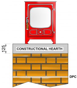
All stoves radiate heat to the floor on which they stand. Traditional fire-proofing arrangements involve building up a brick pier from ground level and topping it off with a 125mm thick constructional hearth. The pier supports the combined weight of the constructional hearth plus the stove.
However, nearly all modern stoves are now certified to not heat the floor to above 100°C which permits a thin (12mm) hearth plate to be used in place of the heavy concrete slabs previously required. Any non-flammable material may be used in the construction of a 12mm hearth plate including steel, glass and slate etc.
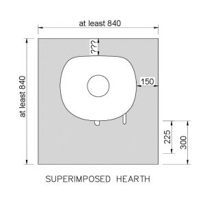 The hearth-plate needs to extend 150mm to either side of a stove and 300mm to the front. A reduced clearance to the front of 225mm is permitted for smaller stoves served by a single door, but 300mm still makes sense due to the tendency for fine ash to ‘creep’ forward onto a carpet.
For freestanding stoves, the hearth-plate must be at least 840mm x 840mm but an additional requirement is that it must project at least 50mm beyond the back of the stove and 150mm to either side as in the diagram at right. The distance at the back will depend upon the ‘clearance to combustibles’ as stated by the stove manufacturer.
2. Firewall
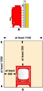
Of course stoves also radiate heat to the back, and require a firewall to be constructed if there are combustible materials that need to be shielded. These include timber studding and plasterboard as are used in the construction of most partition walls.
A firewall must be at lease 1200mm height and 1140mm wide but an additional requirement is that it must extend at least 300mm above a stove and at 300mm to either side.
The firewall must have a thickness of at least 75mm and there must be a clearance of 50mm between the stove and the firewall.
3. Heat shields & clearance to combustibles
The above arrangements have been considerably simplified in recent years due to the fact that stove manufacturers have started to fit heat-shields to their products that drastically reduce the amount of heat they radiate to the floor and to the back. This has permitted the Building Standards to be relaxed. Provided a stove is certified not to heat the floor to above 100°C. the only hearth arrangement required is a floor-plate at least 12mm thick, constructed in non-combustible material (steel, stone & glass are all acceptable).
The dimensions of the hearth have not been altered and continue as for a constructional hearth as detailed in 1. (above).
With regard to heat radiated from the sides of a stove and to the back, most manufacturers now publish a table of ‘clearances to combustibles’ for each of their products and the Building Standards defer to these figures. Thus if a stove can – according to its manufacturer – be mounted 150mm from a timber & plasterboard partition wall, and this clearance is complied with, it will not be necessary to construct a firewall.
A further development is the appearance of wall-hung heat-shields which permit any stove’s ‘clearance to combustibles’ figure to be reduced to 100mm. Thus the need for heavy masonry fire-proofing measures are being gradually replaced by other simpler, more effective techniques. This is particularly welcome on upper floors where the ‘old style’ Building Standards were often extremely difficult and expensive to comply with.
4. Air for Combustion
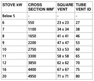
Stoves with a rated output of 5kW or less do not need a fresh air supply. Above 5kW a fresh air vent must be installed with a cross-section of 550mm2 per kW – see Table 1. below.
5. Fluepipe
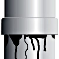
A stove is connected to its chimney using Vitreous Fluepipe (VFP) which must be fitted with the socket to the top. If it is fitted upside down, condensation together with tar & creosote is likely to leak out (as shown).
VFP is made from special grades of low-carbon steel which are expensive to manufacture but can operate safely at sustained temperatures much higher than ordinary mild steel.
Because the material is uninsulated it should be used sparingly and only within a building. Several manufacturers offer a gloss or matt finish in a variety of colours, but VFP can also be over-sprayed with a high temperature stove paint to match the appliance it serves.
6. Flue Components
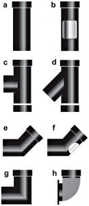
A standard set of VFP components is shown at right;-
a – pipe (available in a variety of lengths)
b – pipe with inspection door
c – 90° Tee (with optional cap at bottom)
d – 135° Tee (with optional cap at bottom)
e – 135° bend (plain)
f – 135° bend with door
g – 90° bend
h is not a VFP component – it is a Vertical Rear Flue Adapter offered by some stove manufacturers for use with their products only and is made from cast iron or pressed steel.
7. Fluepipe clearance to combustibles
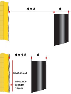
Vitreous or ‘single-wall’ flue-pipe radiates a considerable amount of heat. Its clearance to combustibles is 3 x diameter. Thus a 125mm pipe must be kept 375mm from plasterboard and a 150mm pipe 450mm etc.
The clearance can be halved to 1.5 x diameter when there is between the flue-pipe and the combustible material a non combustible shield that is separated by an air-space of at least 12mm from the combustible material. The shield must extend to either side of the pipe by at least 1.5 times its diameter. For example a shield used with a 125mm pipe must be at least 500mm wide and a shield used with a 150mm pipe must be at least 600mm wide.
8. Stove Connections
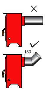
No more than 150mm of horizontal pipe should be used to connect a stove to a chimney. Beyond 150mm the pipe should be angled up at 45° or greater, measured from the horizontal.
9. Access
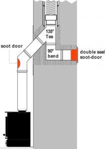
All lengths of flue-pipe must be accessible for cleaning and soot-removal purposes. Where access is not available through the appliance itself it may be necessary to fit flue components with access doors and/or a soot-box with a removable cover-plate.
10. Soot Boxes
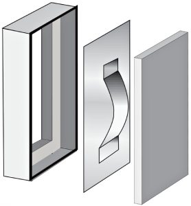
Any soot-box serving a closed stove must be of the double-seal type to prevent cold air from being drawn into the chimney.
An inner plate seats against a peripheral ledge within the box and is held firmly in place by the outer cover which bears onto a compressible strip ‘handle’.
11. Freestanding Installations
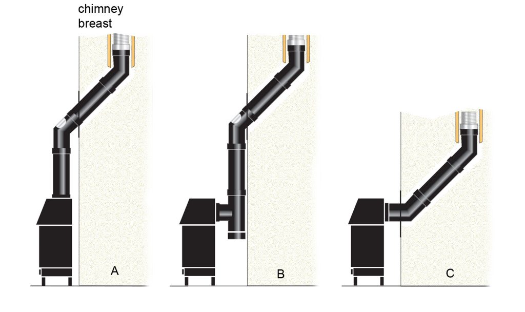
The illustrations below show three possible ways to flue a free-standing stove.
A is best since the short run of vertical pipe harnesses the flue gases when they are in their hottest and most buoyant state. The vertical section should be limited to around 600mm to minimise heat-loss.
B has the advantage of leaving the top of the stove clear but at cost of introducing extra friction via the rear flue connector. It also creates a dead space to the back of the stove and the 90° Tee is likely to require the chimney to be swept from the top down.
C lacks the short vertical ‘boost’ section that both A & B have but may be the only option where the chimney terminates low down and is set far back.
Note that both A & C will permit the chimney to be swept through the stove provided it has a removable throat-plate and a set of ‘bendy’ nylon rods are available that can negotiate the two 45° bends.
12. Fluing through a wall
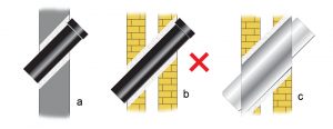
VFP must not be used to connect a stove to a chimney through the outer wall of a building.
Twin-wall sectional chimney is the only material approved for this purpose – and it must be contained within a sleeve that observes the manufacturer’s ‘clearance to combustibles’. For example if the figure quoted is 60mm, the sleeve must have a minimum internal diameter 120mm greater than the outer skin of the chimney. The sleeve must also be ventilated so that heat from the pipe may be safely dissipated.
13. Recessing a stove
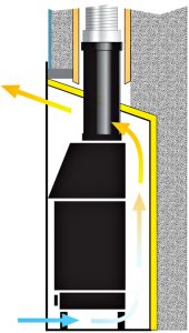
There is much to be said for locating a stove directly under the chimney since this eliminates bends and exposed lengths of flue-pipe thereby guaranteeing the best possible draught performance. Recessing a stove also eliminates any need for a soot-box and provides direct cleaning access to the chimney when the throat-plate is removed.
But recessing must be done with care, otherwise the surrounding masonry will soak up much of the heat produced, the airflow around the stove will be impaired and heat transfer to the room will be severely degraded.
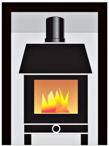 The best way to address these negatives is to house the stove in a ‘convector-box’ constructed in thin-gauge (1.5mm) material that will heat up rapidly. The top should be angled approximately 20° so that as the heat rises it is directed out into the room. The front of the box can be stiffened with a heavier gauge trim 50mm wide that conceals a 25mm wrap of insulating material.
14. Lining the chimney
It is essential to install a low-mass flexible liner into any chimney serving a closed appliance. Smoke from a stove is extremely dense and must be kept as hot as possible. At reduced temperatures wood smoke condenses to a ‘goo’ of moisture, tar and creosote that can create a serious chimney fire hazard and coal smoke condenses to sulphuric acid which attacks the inner surfaces of the chimney. A liner’s purpose is to heat up rapidly to a safe temperature that minimises or hopefully eliminates these problems altogether but if they do occur they will be contained and prevented from damaging the chimney or leaking out at its base.
It is always prudent to run a test-length of flexible flue liner through the chimney early on in the procedures so that a cut-length can then be ordered with confidence. The test length has a nose-cone and pull-cord at either end so that if it jams at any point it can be pulled out the way it went in.
Some times there are ‘sharks tooth’ protrusions in a chimney that will only allow the liner to be pulled in one direction – either up from below or from top down. Running a test helps to determine when this is the case.
15. Checking the overlap direction
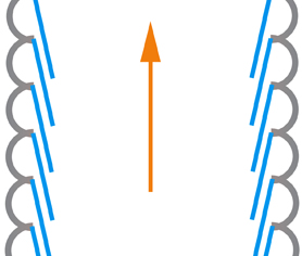 A liner consists of a pair of stainless-steel ribbons wound back- to-back spiral fashion. The outer ribbon is corrugated and the inner one is smooth. The liner must be installed right way up so that the windings over-lap in the right direction. Most liners are marked with an arrow that points up to signify the direction of the flue gases.
16. Installing the liner
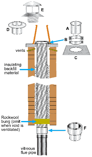
Opinion is divided on the virtues or otherwise of back-filling a liner with insulating material. Granular materials like vermiculite or leca can be poured into the void but with no great expectation that they will distribute evenly around the liner throughout its length.
This is particularly unlikely when there are bends to negotiate. A further concern is that if driving rain manages to penetrate the chimney at any point and wet out the granules they may become a ‘damp-trap’ due to capillary attraction.
On the other hand there is little doubt that in appropriate circumstances back-fill material can help to eliminate cold-spots in the liner and also hold it firm when it is being swept vigorously with a brush.
Whether to backfill or not is perhaps best decided on-site on a case-by-case assessment.
If insulation is omitted the void should be ventilated to keep it dry. A simple technique is to drill a couple of holes into the chimney just below the cope at an angle sufficient to discourage rain penetration. Some short pieces of 22mm diameter copper tube are then tapped in to create a permanent pair of vents.
Once the liner is installed it must be mechanically secured and weather-sealed at its head. A B & C illustrate the ‘plate & clamp’ system that has been widely used for years. A is an insert that is driven into the liner, to prevent it from deforming when the clamp B is tightened and B’s tabs then rest on a heavy steel plate C. which lies on the cope at the base of the chimney. Since this procedure involves removing the pot, an alternative ‘pot-insert’ system D has been developed which sleeves into the liner and caps off the pot onto which it is bedded with a mastic seal.
Weather sealing is vital since any rain water that penetrates into the void will result in heat-loss through the walls of the liner.
The base of the liner terminates into an adapter E with an inner shield to prevent the bristles of a chimney-brush from catching the end of the liner and pushing it out.
The adapter plugs directly into a short length (typically 600mm) of vitreous flue-pipe (VFP) the function of which is to protect the bottom of the liner from any flames that may spill from the stove. (Flexible liners should not be subjected to a service temperature above 450°C.)
17. Acid resistance
Chimney liners are manufactured in two grades of stainless-steel, 316 or 904. 316 is a ‘general purpose’ material widely used in agricultural and marine applications. 904 is formulated to have increased resistance to sulphuric acid and is more expensive.
Since all fossil fuels contain sulphur which converts readily to sulphuric acid, a 904 liner is the safer choice for stoves that are to be run on smokeless fuel or anthracite. It should be noted the ‘slumbering’ a stove on solid fuel greatly increases the concentration of the acids produced andcan shorten the life even of a 904 grade liner.
18. Sectional chimneys
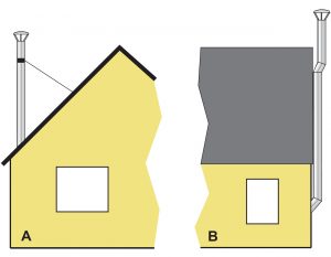
When there is no existing chimney to serve a stove it may be necessary to construct a sectional chimney. These systems work extremely well but have some limitations. One is that domestic versions have a wall thickness of just 25mm which is insufficient to prevent the flue-gases from cooling to below their dew-point when long sections are exposed to the elements – as in A & B.
A further concern in that cold chimneys lose draught rapidly and may in certain conditions cause the flue gases to reverse their direct (the ‘stack effect’), thereby creating a possible carbon monoxide hazard.
These concerns may be addressed simply and safely by accommodating the chimney within a building so that only a minimum amount of its length is exposed to the weather.
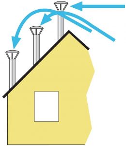 Even here, location is everything. A chimney terminating in clear air near the top of the roof will deliver the best possible results, whereas moving it ‘down-hill’ towards the eaves invites increasing down-draught problems.
In short, the correct and safe location of the chimney largely dictates where the stove should go and any temptation to bend the rules should be firmly resisted!
Further information will be found in our Chimney Section.

